Hyundai Santa Fe (TM): Engine Control System / Engine Control Module (ECM). Schematic diagrams
| ECM Terminal and Input/Output signal |
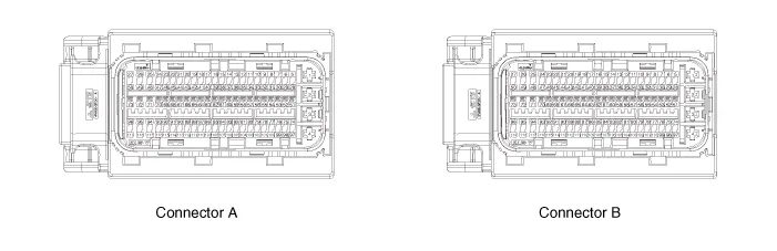
| ECM Terminal Function |
|
Pin No |
Description |
Connected to |
|
1 |
Power ground |
Chassis Ground |
|
2 |
- |
- |
|
3 |
- |
- |
|
4 |
- |
- |
|
5 |
- |
- |
|
6 |
Fuel Sender Signal |
Fuel Sender |
|
7 |
- |
- |
|
8 |
- |
- |
|
9 |
- |
- |
|
10 |
- |
- |
|
11 |
- |
- |
|
12 |
- |
- |
|
13 |
- |
- |
|
14 |
- |
- |
|
15 |
Stop Lamp Signal |
Stop Lamp |
|
16 |
Brake Test Switch |
Brake Switch |
|
17 |
|
|
|
18 |
- |
|
|
19 |
- |
|
|
20 |
Output Speed (Supply) |
ATM Solenoid Valve (Otput Speed) |
|
21 |
Input Speed (Supply) |
ATM Solenoid Valve (Input Speed) |
|
22 |
- |
- |
|
23 |
- |
- |
|
24 |
- |
- |
|
25 |
- |
- |
|
26 |
- |
- |
|
27 |
[A/T] SOL. (PWR1) |
ATM Solenoid Valve |
|
28 |
- |
- |
|
29 |
- |
- |
|
30 |
- |
- |
|
31 |
- |
- |
|
- |
- |
|
|
32 |
- |
- |
|
33 |
- |
- |
|
34 |
- |
- |
|
35 |
- |
- |
|
36 |
- |
- |
|
37 |
- |
- |
|
38 |
APT (Signal) |
A/C Pressure Transducer (APT) |
|
39 |
- |
- |
|
40 |
- |
- |
|
41 |
- |
- |
|
42 |
- |
- |
|
43 |
[A/T] Output Speed (Signal) |
Engine Control Relay |
|
44 |
[A/T] Input Speed (Signal) |
ATM Solenoid Valve |
|
45 |
- |
- |
|
46 |
- |
- |
|
47 |
- |
- |
|
48 |
[A/T] SOL. (VFS_26B) |
ATM Solenoid Valve |
|
49 |
[A/T] SOL. (VFS_OD) |
ATM Solenoid Valve |
|
50 |
[A/T] SOL. (VFS_PWR2) |
ATM Solenoid Valve |
|
51 |
- |
- |
|
52 |
- |
- |
|
53 |
- |
- |
|
54 |
- |
- |
|
55 |
- |
- |
|
56 |
APS (APS. 2 Ground) |
Accelerator Position Sensor (APS) |
|
57 |
APS (APS. 1 Ground) |
Accelerator Position Sensor (APS) |
|
58 |
- |
- |
|
59 |
- |
- |
|
60 |
- |
- |
|
61 |
APT (Ground) |
A/C Pressure Transducer (APT) |
|
62 |
- |
- |
|
63 |
- |
- |
|
64 |
- |
- |
|
65 |
- |
- |
|
66 |
- |
- |
|
67 |
- |
- |
|
68 |
- |
- |
|
69 |
[A/T] SOL. (OTS (-)) |
ATM Solenoid Valve |
|
70 |
[A/T] SOL. (OTS (+)) |
ATM Solenoid Valve |
|
71 |
- |
- |
|
72 |
[A/T] SOL. (VFS_LINE) |
ATM Solenoid Valve |
|
73 |
[A/T] SOL. (VFS_UD) |
ATM Solenoid Valve |
|
74 |
Start Relay Control |
B/Alarm Relay |
|
75 |
- |
- |
|
76 |
Vehicle Speed Signal |
IBU & ESP Control Module |
|
77 |
- |
- |
|
78 |
- |
- |
|
79 |
APS (APS. 2 Ground) |
Accelerator Position Sensor (APS) |
|
80 |
APS (APS. 1 Ground) |
Accelerator Position Sensor (APS) |
|
81 |
- |
- |
|
82 |
O2 Sensor (Up) (V_N) |
Oxygen Sensor (Up) |
|
83 |
O2 Sensor (Down) (Ground) |
Oxygen Sensor (Down) |
|
84 |
O2 Sensor (Up) (V_RC) |
Oxygen Sensor (Up) |
|
85 |
- |
- |
|
86 |
- |
- |
|
87 |
- |
- |
|
88 |
- |
- |
|
89 |
- |
- |
|
90 |
- |
- |
|
91 |
- |
- |
|
92 |
- |
- |
|
93 |
- |
- |
|
94 |
[A/T] SOL. Power (SS-B) |
ATM Solenoid Valve |
|
95 |
[A/T] SOL. (VFS_35R) |
ATM Solenoid Valve |
|
96 |
Memory Power |
PCB Block |
|
97 |
Wiper 'P' Input |
PCB Block |
|
98 |
- |
- |
|
99 |
- |
- |
|
100 |
- |
- |
|
101 |
- |
- |
|
102 |
APS (APS. 2 Supply) |
Accelerator Position Sensor (APS) |
|
103 |
APS (APS. 1 Supply) |
Accelerator Position Sensor (APS) |
|
104 |
APT (Supply) |
A/C Pressure Transducer (APT) |
|
105 |
O2 Sensor (Up) (V_G) |
Oxygen Sensor (Up) |
|
106 |
O2 Sensor (Down) (Signal) |
Oxygen Sensor (Down) |
|
107 |
O2 Sensor (Up) (V_IP) |
Oxygen Sensor (Up) |
|
108 |
- |
- |
|
109 |
Knock Sensor (Ground) |
Knock Sensor (KS) |
|
110 |
Knock Sensor (Signal) |
Knock Sensor (KS) |
|
111 |
- |
- |
|
112 |
- |
- |
|
113 |
- |
- |
|
114 |
- |
- |
|
115 |
- |
- |
|
116 |
- |
- |
|
117 |
[A/T] SOL. (SS-A) |
ATM Solenoid Valve |
|
118 |
[A/T] SOL. (VFS_T/CON) |
ATM Solenoid Valve |
|
119 |
Memory Power |
PCB Block |
|
Pin No |
Description |
Connected to |
|
1 |
Engine Control Relay 'ON' Input |
Engine Control Relay |
|
2 |
Engine Control Relay 'ON' Input |
Engine Control Relay |
|
3 |
Ground |
Ground |
|
4 |
Ground |
Ground |
|
5 |
Engine Control Relay 'ON' Input |
PCB Block |
|
6 |
P-CAN (High) |
P-CAN (High) |
|
7 |
P-CAN (Low) |
P-CAN (Low) |
|
8 |
- |
- |
|
9 |
- |
- |
|
10 |
- |
- |
|
11 |
- |
- |
|
12 |
- |
- |
|
13 |
OPTS (Signal) |
Oil Pressure Switch |
|
14 |
CMP (IN) (Signal) |
Camshaft Position Sensor (Intake) |
|
15 |
CMP (EX) (Signal) |
Camshaft Position Sensor (Exhaust) |
|
16 |
ETC Motor & Throttle Position Sensor.1 Signal |
ETC Motor & Throttle Position Sensor |
|
17 |
ETC Motor & Throttle Position Sensor Supply |
ETC Motor & Throttle Position Sensor |
|
18 |
- |
- |
|
19 |
- |
- |
|
20 |
- |
- |
|
21 |
- |
- |
|
22 |
- |
- |
|
23 |
- |
- |
|
24 |
Ignition Coil #1 (Control) |
Ignition Coil #1 |
|
25 |
O2 Sensor (Up) (Heater) |
Oxygen Sensor (Up) |
|
26 |
O2 Sensor (Down) (Heater) |
Oxygen Sensor (Down) |
|
27 |
- |
- |
|
28 |
- |
- |
|
29 |
Local-CAN (High) |
Electronic ATM Shift Lever, SCU (High) |
|
30 |
Local-CAN (Low) |
Electronic ATM Shift Lever, SCU (Low) |
|
31 |
- |
- |
|
32 |
- |
- |
|
33 |
- |
- |
|
34 |
WTS #1 (Signal) |
Engine Coolant Temperature Sensor |
|
35 |
Sensor Power : Map, CMP (In), CKP |
Sensor Power : Map, CMP (In), CKP |
|
36 |
- |
- |
|
37 |
CMP (In) (Ground) |
Camshaft Position Sensor (Intake) |
|
38 |
CMP (EX) (Ground) |
Camshaft Position Sensor (Exhaust) |
|
39 |
ETC Motor & Throttle Position Sensor.2 Signal |
ETC Motor & Throttle Position Sensor |
|
40 |
- |
- |
|
41 |
- |
- |
|
42 |
Fuel Pump Relay Control |
Fuel Pump Relay |
|
43 |
Engine Control Relay Control |
Engine Control Relay |
|
44 |
- |
- |
|
45 |
- |
- |
|
46 |
A/C Relay Control |
A/C Relay |
|
47 |
Ignition Coil #3 (Control) |
Ignition Coil #3 |
|
48 |
ETC DC Motor (+) |
ETC Motor |
|
49 |
ETC DC Motor (-) |
ETC Motor |
|
50 |
- |
- |
|
51 |
ON/Start (Input) |
ON/Start (Input) |
|
52 |
- |
- |
|
53 |
- |
- |
|
54 |
- |
- |
|
55 |
- |
- |
|
56 |
- |
- |
|
57 |
WTS #1 (Ground) |
Engine Coolant Temperature Sensor |
|
58 |
MAP & IAT Ground |
MAP Sensor |
|
59 |
- |
- |
|
60 |
- |
- |
|
61 |
- |
- |
|
62 |
ETC (TPS Groud) |
ETC Motor & Throttle Position Sensor |
|
63 |
- |
- |
|
64 |
- |
- |
|
65 |
Start Relay (Low Side) |
Start Relay |
|
66 |
- |
- |
|
67 |
- |
- |
|
68 |
- |
- |
|
69 |
- |
- |
|
70 |
OCV Control (EX) |
CVVT Oil Control Valve (OCV) |
|
71 |
OCV Control (IN) |
CVVT Oil Control Valve (OCV) |
|
72 |
- |
- |
|
73 |
- |
- |
|
74 |
- |
- |
|
75 |
Local-CAN2 (High) |
Can Check |
|
76 |
Local-CAN2 (Low) |
Can Check |
|
77 |
Alternator (IN) |
Alternator |
|
78 |
- |
- |
|
79 |
- |
- |
|
80 |
CKP (Ground) |
Crankshaft Position Sensor (CKPS) |
|
81 |
MAP Sensor (Signal) |
MAP Sensor |
|
82 |
Ignition Coil #1/#4 (Feedback) |
Ignition Coil #1 / #4 (Feedback) |
|
83 |
- |
- |
|
84 |
- |
- |
|
85 |
- |
- |
|
86 |
- |
- |
|
87 |
- |
- |
|
88 |
C/FAN Motor (PWM Signal) |
C/FAN Motor |
|
89 |
PCSV Control |
Purge Control Solanoid Valve |
|
90 |
CCV Control (Not Used) |
Canister Close Valve |
|
91 |
- |
- |
|
92 |
VIS Control |
Variable Intake Solenoid Valve (VIS) |
|
93 |
Ignition Coil #4 Control |
Ignition Coil #4 |
|
94 |
Injector Coil #4 Control |
Injector Coil #4 |
|
95 |
- |
- |
|
96 |
- |
- |
|
97 |
- |
- |
|
98 |
- |
- |
|
99 |
IMMO. Data Line |
Immobilizer |
|
100 |
- |
- |
|
101 |
- |
- |
|
102 |
- |
- |
|
103 |
Crankshaft Position Sensor (CKPS) signal input |
Crankshaft Position Sensor (CKPS) |
|
104 |
IAT Sensor |
MAP Sensor |
|
105 |
Ignition Coil #2 / #3 (Feedback) |
Ignition Coil #2 / #3 (Feedback) |
|
106 |
- |
- |
|
107 |
- |
- |
|
108 |
CMP (EX) (Supply) |
Camshaft Position Sensor (CMPS) |
|
109 |
FTPS (Not Used) |
Fuel Tank Pressure Sensor (FTPS) |
|
110 |
Engine RPM Signal |
Engine RPM Signal |
|
111 |
- |
- |
|
112 |
- |
- |
|
113 |
- |
- |
|
114 |
- |
- |
|
115 |
Thermostat PWM |
Electronic Thermostat |
|
116 |
Ignition Coil #2 Control |
Ignition Coil #2 |
|
117 |
Injector Coil #1 Control |
Injector Coil #1 |
|
118 |
Injector Coil #3 Control |
Injector Coil #3 |
|
119 |
Injector Coil #2 Control |
Injector Coil #2 |
Components Location 1. ECM (Engine Control Module) 2. Manifold Absolute Pressure Sensor (MAPS) 3. Intake Air Temperature Sensor (IATS) 4.
Removal • If you replace the PCM, you must perform oil pressure characteristics back up & input (TCU Replacement).
Other information:
Hyundai Santa Fe (TM) 2019-2023 Service and Repair Manual: Rear Wiper/Washer
Components and components location Component Location 1. Rear wiper arm nut 2. Rear wiper arm & blade 3. Rear wiper grommet 4. Rear wiper motor assembly Rear Wiper Motor. Repair procedures Inspection Rear Wiper Motor 1.
Hyundai Santa Fe (TM) 2019-2023 Service and Repair Manual: General safety information and caution
Instructions (R-134a) When Handling Refrigerant 1. R-134a liquid refrigerant is highly volatile. A drop on the skin of your hand could result in localized frostbite. When handling the refrigerant, be sure to wear gloves.
Categories
- Manuals Home
- Hyundai Santa Fe Owners Manual
- Hyundai Santa Fe Service Manual
- Lane Following Assist (LFA)
- Instrument cluster
- Rear seats
- New on site
- Most important about car
