Hyundai Santa Fe (TM): Emission Control System
Hyundai Santa Fe (TM) 2019-2023 Service and Repair Manual / Emission Control System
Description and operation
| Description |
Emissions Control System consists of three major systems.
| • |
The Crankcase Emission Control System prevents blow-by gas from releasing
into the atmosphere. This system recycles gas back into the intake manifold
(Closed Crankcase Ventilation Type).
|
| • |
The Evaporative Emission Control System prevents evaporative gas from
releasing into the atmosphere. This system burns gas at appropriate
engine operating condition after gathering it in the canister.
|
| • |
The Exhaust Emission Control System converts the three pollutants [hydrocarbons
(HC), carbon monoxide (CO), and oxides of nitrogen (NOx)] into harmless
substances by using the 3-way catalytic converter.
|
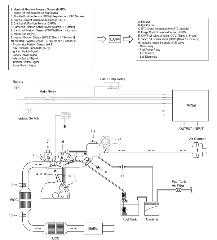
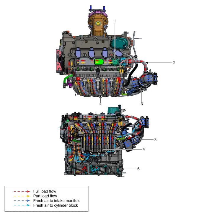
Components and components location
| Components Location |
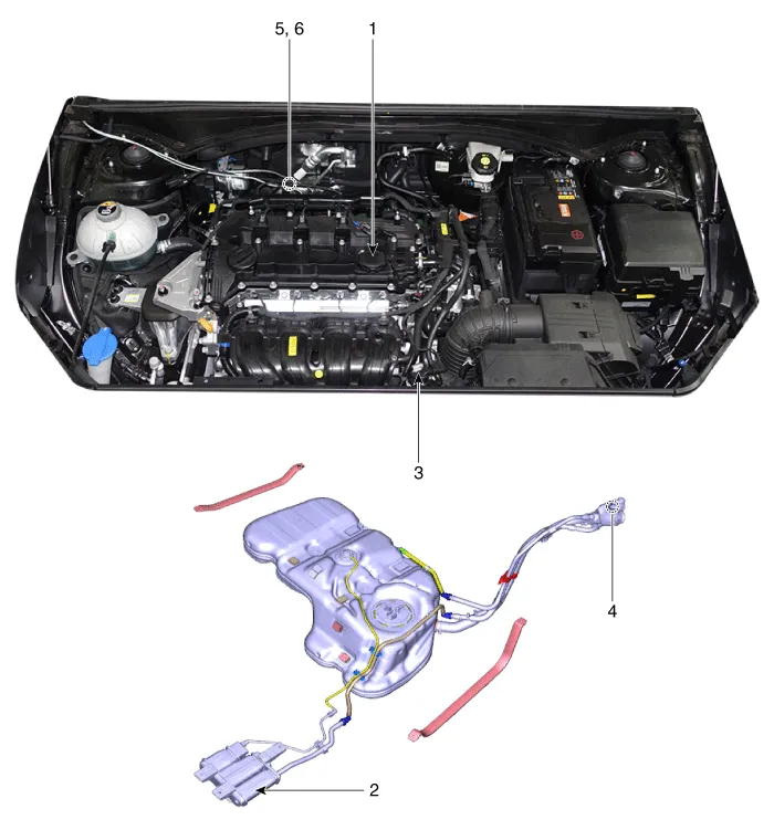
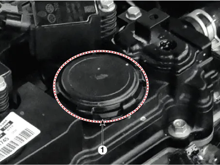
| 1. Crankcase
pressure regulating valve (PRV) 2. Canister 3. Purge control solenoid valve (PCSV) |
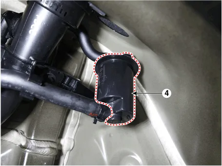
4. Fuel tank
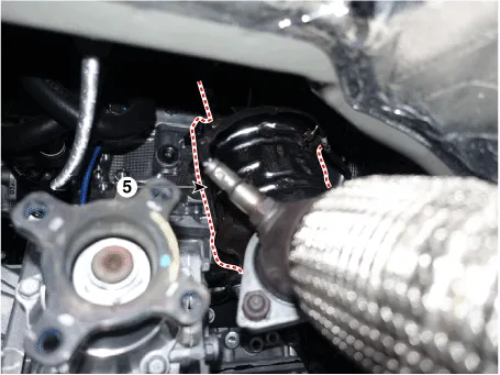
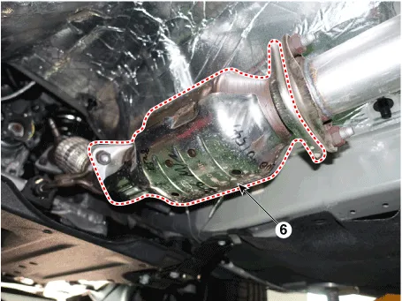
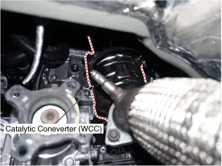
air filter 5. Catalytic converter (WCC) 6. Catalytic converter (UCC) |
|
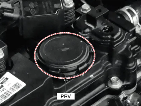
1. Crankcase Pressure Regulating Valve (PRV) |
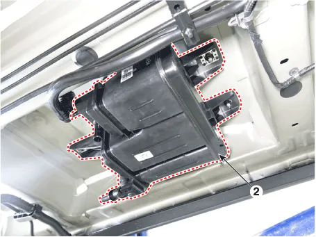
2. Canister |
|
|
|
|
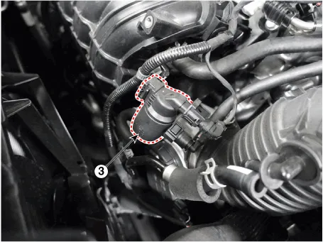
3. Purge control solenoid valve (PCSV) |
4. Fuel tank air filter |
|
|
|
|
5. Catalytic converter (WCC) |
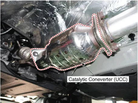
6. Catalytic converter (UCC) |
|
|
|
Troubleshooting
| Troubleshooting |
|
Symptom |
Suspect area |
|
Engine will not start or hard to start |
Vapor hose damaged or disconnected |
|
Engine struggles to start |
Malfunction of the Purge Control Solenoid Valve |
|
Rough idle or engine stalls |
Vapor hose damaged or disconnected |
|
Malfunction of the PCV valve |
|
|
Rough idle |
Malfunction of the Evaporative Emission Control System |
|
Excessive oil consumption |
Positive crankcase ventilation line clogged |
Specifications
| Specifications |
Purge Control Solenoid Valve (PCSV)
â–· Specification
|
Item |
Specification |
|
Coil Resistance (Ω) |
20.0 - 22.0 [20°C (68°F)] |
Schematic diagrams
| Schematic Diagram |
Crankcase Emission Control System
Schematic diagrams
| Schematic Diagram |
| 1. PCV Valve 2. Breather hose 3. Air intake hose |
4. Intake maifold 5. Air breather hose 6. Cylinder block |
Positive Crankcase Ventilation (PCV) Valve. Description and operation
| Description |
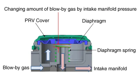
Pressure Regulating Valve (PRV) is installed to prevent the over pressure of
combustion gas through the piston ring and onto the crankcase.
| Operation Principle |
|
Engine Condition |
Stop |
Idle or Deceleration |
Normal operating condition |
Accelerating in the high load area |
|
Intake manifold pressure |
0 |
High |
Appropriate |
Low |
|
PRV (Diaphragm) |
Full open |
A little open |
Appropriate open |
Considerable open |
|
Amount of blow-by gas |
0 |
A little |
Middle |
A lot |
|
Diaphragm component part |
|
|||
Positive Crankcase Ventilation (PCV) Valve. Repair procedures
| Removal |
| 1. |
Remove the cylinder head cover.
(Refer to Engine Mechanical System - "Cylinder Head Cover")
|
| Installation |
| 1. |
Install in the reverse order of removal.
|
Crankcase Check Valve. Repair procedures
| Removal and Installation |
|

| 1. |
Disconnect the battery (-) terminal.
|
| 2. |
Remove the engine room under cover.
(Refer to Engine And Transaxle Assembly - "Engine Room Under Cover")
|
| 3. |
Remove the drive belt.
(Refer to Drive Belt System - "Drive Belt")
|
| 4. |
Remove the compressor mounting bolts.
(Refer to Heating, Ventilation and Air Conditioning - "Compressor")
|
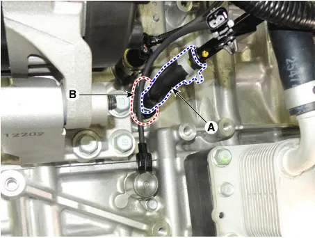
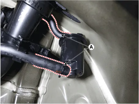
| 5. |
Disconnect the crankcase check valve hose (A) and then remove the crankcase
check valve (B).
|

Evaporative Emission Control System
Description and operation
| Description |
Evaporative Emission Control System prevents fuel vapor stored in fuel tank
from vaporizing into the atmosphere. When the fuel evaporates in the fuel tank,
the vapor passes through vent hoses or tubes to the canister filled with charcoal
and the canister temporarily holds the vapor in the charcoal.
If ECM determines to draw the gathered vapor into the combustion chambers during
certain operating conditions, it will use vacuum in intake manifold to move
it.
Schematic diagrams
| Schematic Diagram |
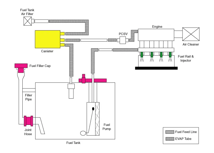
Canister
Canister is filled with charcoal and absorbs evaporated vapor in fuel tank.
The gathered fuel vapor in canister is drawn into the intake manifold by the
ECM/PCM when appropriate conditions are set.
Purge Control Solenoid Valve (PCSV)
Purge Control Solenoid Valve (PCSV) is installed in the passage connecting canister
and intake manifold. It is a duty type solenoid valve and is operated by ECM/PCM
signal.
To draw the absorbed vapor into the intake manifold, the ECM/PCM will open the
PCSV, otherwise the passage remains closed.
Fuel Filler Cap
A ratchet tightening device on the threaded fuel filler cap reduces the chances
of incorrect installation, which would seal the fuel filler. After the gasket
on the fuel filler cap and the fill neck flange contact each other, the ratchet
produces a loud clicking noise indicating the seal has been set.
Canister. Repair procedures
| Removal |
|
| 1. |
Turn the ignition switch OFF and disconnect the battery (-) terminal.
|
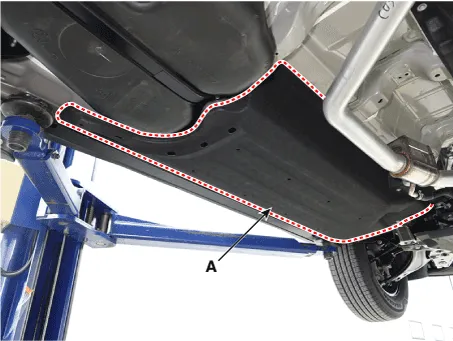
| 2. |
Remove the floor under cover (A).
|
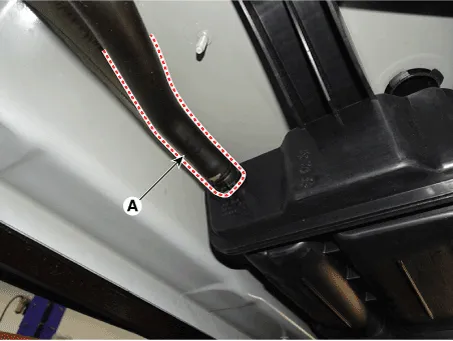
| 3. |
Disconnect the vent hose (A).
|
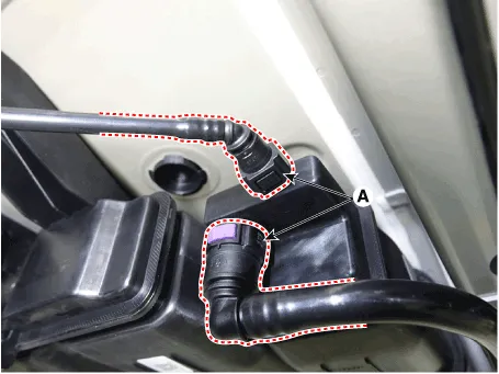
| 4. |
Disconnect the vapor hose quick-connector (A).
|
| 5. |
Remove the canister (A) after loosening the mounting nuts.
|

| Installation |
| 1. |
Install in the reverse order of removal.
|
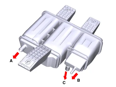
| Inspection |
| 1. |
Check for the following items visually.
A : Canister ↔ Atmosphere
B : Canister ↔ Fuel Tank
C : Canister ↔ Intake Manifold
|
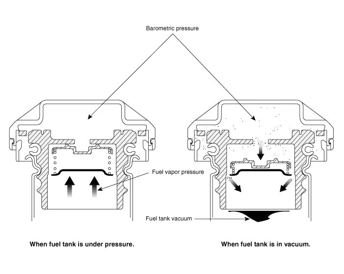
Fuel Filler Cap. Description and operation
| Description |
A ratchet tightening device on the threaded fuel filler cap reduces the chances
of incorrect installation, which seals the fuel filler. After the gasket on
the fuel filler cap and the filler neck flange contact each other, the ratchet
produces a loud clicking noise indicating the seal has been set.
Fuel Tank Air Filter. Repair procedures
| Removal |
|
| 1. |
Turn the ignition switch OFF and disconnect the battery (-) terminal.
|
| 2. |
Lift the vehicle.
|
| 3. |
Remove the rear-left wheel & tire and wheel house cover.
|
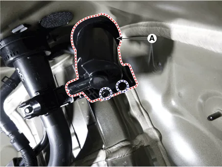
| 4. |
Separate the ventilation hoses (A).
|
| 5. |
Remove the fuel tank air filter (A) after loosening the mounting bolts.
|
| Installation |
| 1. |
Install in the reverse order of removal.
|
Exhaust Emission Control System
Description and operation
| Description |
Exhaust emissions (CO, HC, NOx) are controlled by a combination of engine modifications
and the addition of special control components.
Modifications to the combustion chamber, intake manifold, camshaft and ignition
system form the basic control system.
These items have been integrated into a highly effective system which controls
exhaust emissions while maintaining good drivability and fuel economy.
Air/Fuel Mixture Control System [Multiport Fuel Injection (MFI) System]
The MFI system uses signals from the heated oxygen sensor to activate and control
the injector installed in the manifold for each cylinder, thus precisely regulating
the air/fuel mixture ratio and reducing emissions.
This in turn allows the engine to produce exhaust gas of the proper composition
to permit the use of a three way catalyst. The three way catalyst is designed
to convert the three pollutants [hydrocarbons (HC), carbon monoxide (CO), and
oxides of nitrogen (NOx)] into harmless substances. There are two operating
modes in the MFI system.
| 1. |
Open Loop air/fuel ratio is controlled by information pre-programmed
into the ECM.
|
| 2. |
Closed Loop air/fuel ratio is constantly adjusted by the ECM based on
information supplied by the oxygen sensor.
|
Catalytic Converter. Description and operation
| Description |
The catalytic converter of the gasoline engine is a three way catalyst. It oxidizes
carbon monoxide and hydrocarbons (HC), and separates oxygen from the oxides
of nitrogen (NOx).
Catalytic Converter. Repair procedures
| Removal |
[Catalytic Converter (WCC)]
| 1. |
Remove the exhaust manifold.
(Refer to Engine Mechanical System - "Exhaust Manifold")
|
[Catalytic Converter (UCC)]
| 1. |
Remove the Center Muffler.
(Refer to Engine Mechanical System - "Center Muffler")
|
| Installation |
| 1. |
Install in the reverse order of removal.
|
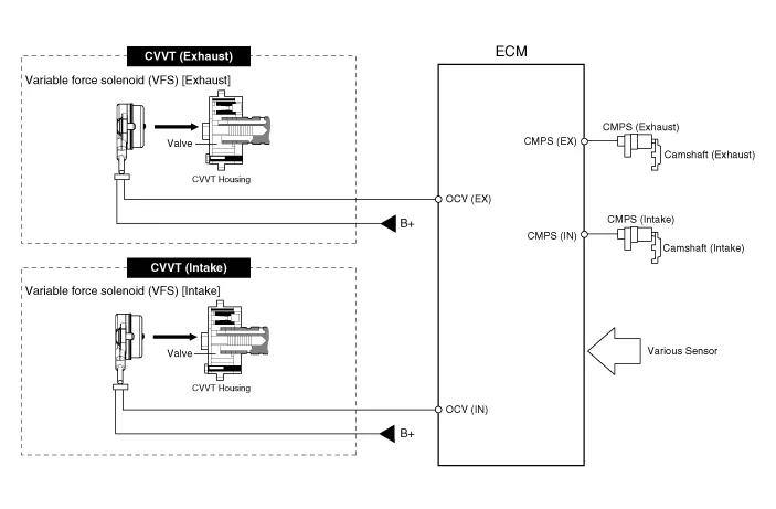
CVVT (Continuously Variable Valve Timing) System. Description and operation
| Description |
Continuous Variable Valve Timing (CVVT) system advances or retards the valve
timing of the intake and exhaust valve in accordance with the ECM control signal
which is calculated by the engine speed and load.
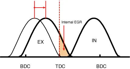
By controlling CVVT, the valve over-lap or under-lap occurs, which makes better
fuel economy and reduces exhaust gases (NOx, HC) and improves engine performance
through reduction of pumping loss, internal EGR effect, improvement of combustion
stability, improvement of volumetric efficiency, and increase of expansion work.
This system consist of
| – |
the CVVT Oil Control Valve (OCV) which supplies the engine oil to the
cam phaser or runs out the engine oil from the cam phaser in accordance
with the ECM PWM (Pulse With Modulation) control signal,
|
| – |
the CVVT Oil Temperature Sensor (OTS) which measures the engine oil
temperature,
|
| – |
and the Cam Phaser which varies the cam phase by using the hydraulic
force of the engine oil.
|
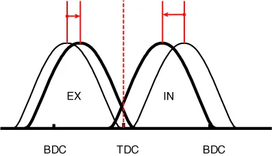
The engine oil getting out of the CVVT oil control valve varies the cam phase
in the direction (Intake Advance/Exhaust Retard) or opposite direction (Intake
Retard/Exhaust Advance) of the engine rotation by rotating the rotor connected
with the camshaft inside the cam phaser.
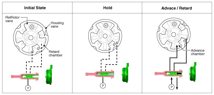
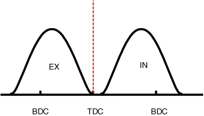
| Operation Principle |
The CVVT has the mechanism rotating the rotor vane with hydraulic force generated
by the engine oil supplied to the advance or retard chamber in accordance with
the CVVT oil control valve control.
|

| [CVVT System Mode] |
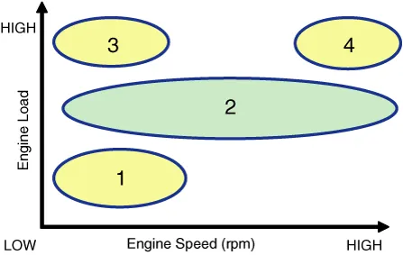
|
(1) Low Speed / Low Load |
(2) Part Load |
|
|
|
|
(3) Low Speed / High Load |
(4) High Speed / High Load |
|
|
|
|
Driving Condition |
Exhaust Valve |
Intake Valve |
||
|
Valve Timing |
Effect |
Valve Timing |
Effect |
|
|
(1) Low Speed /Low Load |
Completely Advance |
* Valve Under-lap * Improvement of combustion stability |
Completely Retard |
* Valve Under-lap * Improvement of combustion stability |
|
(2) Part Load |
Retard |
* Increase of expansion work * Reduction of pumping loss * Reduction of HC |
Retard |
* Reduction of pumping loss |
|
(3) Low Speed /High Load |
Retard |
* Increase of expansion work |
Advance |
* Prevention of intake back flow (Improvement of volumetric efficiency) |
|
(4) High Speed /High Load |
Advance |
* Reduction of pumping loss |
Retard |
* Improvement of volumetric efficiency |
Description and operation Description The ignition coil is a kind of small transformer that transforms the battery voltage to 30 kV or more to create a spark in the spark plug gap in the cylinder.
Other information:
Hyundai Santa Fe (TM) 2019-2023 Service and Repair Manual: Description and operation
Hyundai Santa Fe (TM) 2019-2023 Service and Repair Manual: General safety information and caution
General Safety Information and Caution 1. Be careful when driving the vehicle using the smart cruise control system as follows. (1) On curves or inclines/declines • The smart cruise control system may have limits
Categories
- Manuals Home
- Hyundai Santa Fe Owners Manual
- Hyundai Santa Fe Service Manual
- Troubleshooting
- Automatic Transaxle Control System
- Lane Following Assist (LFA)
- New on site
- Most important about car

Copyright © 2026 www.hsafe4.com - 0.0276