Hyundai Santa Fe (TM): Air conditioning System / Components and components location
| Component Location Index |
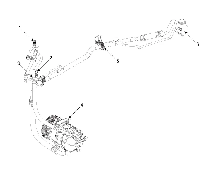
| 1. Service port
(High pressure) 2. A/C pressure transducer (APT) 3. Service port (Low pressure) |
4. Compressor 5. Suction & Liquid pipe assembly 6. Expansion valve |
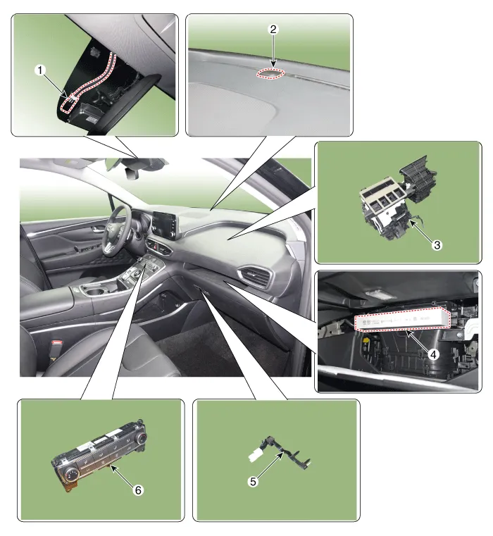
| 1. Auto defogging
sensor 2. Photo Sensor 3. Heater & Blower unit |
4. Air filter 5. Evaporator Temperature Sensor 6. Heater & A/C control unit |
Refrigeration Cycle
Refrigerant System Service Basics (R-134a) Refrigerant Recovery Use only service equipment that is U.L-listed and is certified to meet the requirements of SAE J2210 to remove HFC-134a(R-134a) from the air conditioning system.
Other information:
Hyundai Santa Fe (TM) 2019-2023 Service and Repair Manual: General safety information and caution
Instructions (R-134a) When Handling Refrigerant 1. R-134a liquid refrigerant is highly volatile. A drop on the skin of your hand could result in localized frostbite. When handling the refrigerant, be sure to wear gloves.
Hyundai Santa Fe (TM) 2019-2023 Service and Repair Manual: Photo Sensor. Repair procedures
Inspection 1. Emit intensive light toward the photo sensor using a lamp, and check the output voltage change. 2. The voltage will rise with higher intensive light and reduce with lower intensive light.
Categories
- Manuals Home
- Hyundai Santa Fe Owners Manual
- Hyundai Santa Fe Service Manual
- Emission Control System
- Troubleshooting
- Battery. Specifications
- New on site
- Most important about car
