Hyundai Santa Fe (TM): Heater / Auto Defogging Actuator. Repair procedures
Hyundai Santa Fe (TM) 2019-2023 Service and Repair Manual / Heating,Ventilation And Air Conditioning / Heater / Auto Defogging Actuator. Repair procedures
| Inspection |
| 1. |
Turn the ignition switch OFF.
|
| 2. |
Disconnect the auto defogging connector.
|
| 3. |
Verify that the auto defogging actuator operates to the open position
when connecting 12V to terminal 3 and grounding terminal 6.
Verify that the auto defogging actuator operates to the close position
when connected in reverse.
|

| 4. |
Connect the auto defogging actuator connector.
|
| 5. |
Turn the ignition switch ON.
|
| 6. |
Check the voltage between terminals 5 and 4.
Specification
|

| 7. |
If the measured voltage is not within specification, check the operation
by replacing the existing auto defogging actuator with a new genuine
part. After that, determine whether replacement of the auto defogging
actuator is required or not.
|
| Replacement |
| 1. |
Disconnect the negative (-) battery terminal.
|
| 2. |
Remove the main crash pad assembly.
(Refer to Body - "Main Crash Pad Assembly")
|
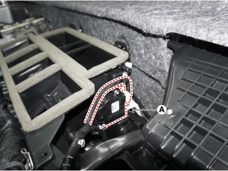
| 3. |
Press the lock pin and separate the connector (A) and loosen the mounting
screws and remove the auto defogging actuator (B).
|
| 4. |
Install in the reverse order of removal.
|
Components Location 1. Auto defogging actuator
Other information:
Hyundai Santa Fe (TM) 2019-2023 Service and Repair Manual: Description and operation
Description • PDW consists of 8 sensors (front : 4 units, rear : 4 units) that are used to detect obstacles and transmit the result in three separate warning levels, the first, second and third to IBU via LIN communication.
Hyundai Santa Fe (TM) 2019-2023 Service and Repair Manual: Surround View Monitor (SVM) Unit. Repair procedures
Removal 1. Disconnect the negative (-) battery terminal. 2. Remove the carash pad lower panel. (Refer to Body - "Crash Pad Lower Panel") 3. Remove the crash pad center panel.
Categories
- Manuals Home
- Hyundai Santa Fe Owners Manual
- Hyundai Santa Fe Service Manual
- Engine Control/Fuel System
- 4 Wheel Drive (4WD) System
- Vehicle Information, Consumer Information and Reporting Safety Defects
- New on site
- Most important about car

Copyright © 2025 www.hsafe4.com - 0.0219