Hyundai Santa Fe (TM): Audio / Audio Remote Control. Schematic diagrams
| Circuit Diagram |
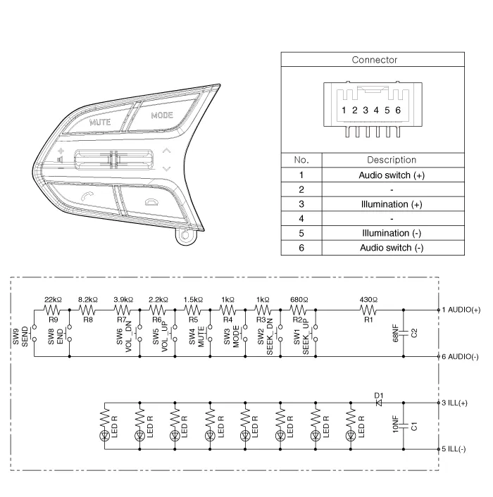
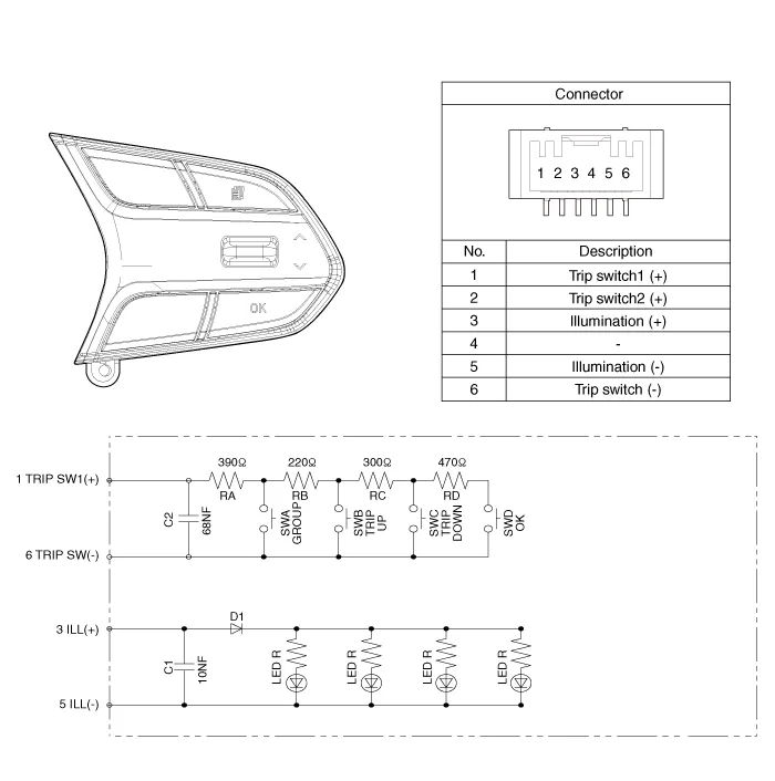
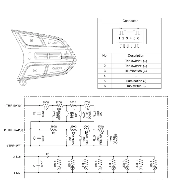
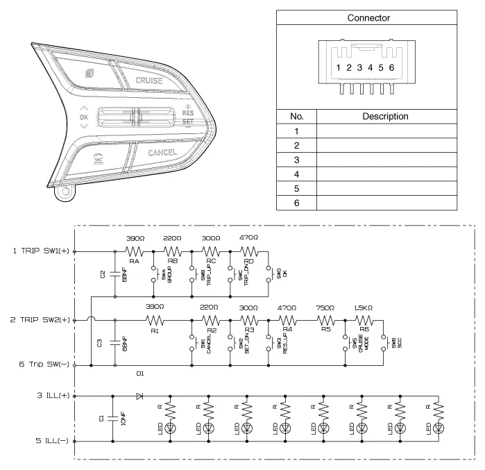
Components 1. Remote control switch (LH : Audio) 2. Remote control switch (RH : Cruise+Flex)
Inspection 1. Check for resistance between terminals in left switch position. [Audio/Bluetooth] Switch Connector terminal Resistance (¬Ī 3%) SEEK Up 1 - 6 430 ‚Ą¶ SEEK Down 1 - 6 1.
Other information:
Hyundai Santa Fe (TM) 2019-2023 Service and Repair Manual: PTC Heater (Diesel only). Repair procedures
Inspection Operating Logic Test (Manual only) Inspect the PTC operation with the confirmation logic below : 1. Entering (1) Set the mode to FLOOR. (2) Set the temperature to MAX HOT.
Hyundai Santa Fe (TM) 2019-2023 Service and Repair Manual: Warning Indicator. Repair procedures
Inspection 1. Disconnect the negative (-) battery terminal. 2. Remove the front door trim. (Refer to Body - "Front door trim") 3. Disconnect the power door mirror connector from the harness BCW indicator
Categories
- Manuals Home
- Hyundai Santa Fe Owners Manual
- Hyundai Santa Fe Service Manual
- Engine Control/Fuel System
- Engine Electrical System
- Seats & Safety System
- New on site
- Most important about car
