Hyundai Santa Fe: Automatic Transaxle System (SBC) / Troubleshooting
Features a fail-safe mechanism that provides "limp-home" 4th gear hold to enable
the vehicle to be driven to the owner's home or dealer shop.
| •
|
Fail-Safe : The TCM provides 4th gear hold and Reverse gear
in the event of a malfunction.
|
| •
|
Limp Home : Maintains minimal functionality (Drive (4th gear
hold), Reverse) in the event of a malfunction, making it possible
for the vehicle to reach the dealer shop.
|
|
Trouble symptom
|
Suspect area
|
Remedy
|
Shift delay
|
Damaged clutch / brake
|
Replace the brake or clutch.
|
Faulty hydraulic control
|
Inspect the solenoid valve.
|
Faulty hydraulic supply
|
Check the fluid level.
|
Not performed TCM learning
|
TCM learning is required.
|
Vibration of the vehicle when shifting
|
Damaged clutch / brake
|
Replace the brake or clutch.
|
Not performed TCM learning
|
TCM learning is required.
|
Faulty hydraulic control
|
Inspect the solenoid valve.
|
Faulty hydraulic supply
|
Check the fluid level.
|
Fixed gear (shift impossible)
|
Faulty hydraulic control
|
Inspect the solenoid valve.
|
Replace the solenoid valve or valve body.
|
Faulty harness & connector connection
|
Check the harness & connector of transaxle.
|
Faulty TCM
|
Replace the TCM
|
Faulty CAN Communication
|
Inspect the CAN communication line.
|
limited gear (shift possible)
|
Faulty position sensor & position switch
|
Inspect the position sensor & position switch
|
Faulty input & output speed sensor
|
Inspect the input & output speed sensor.
|
Faulty harness & connector connection
|
Check the harness & connector of transaxle.
|
Poor acceleration
|
Faulty hydraulic control
|
Inspect the solenoid valve.
|
Faulty hydraulic supply
|
Check the fluid level.
|
Faulty oil pump
|
Replace the oil pump.
|
Transaxle Control Module (TCM) is in constant communication with the control
system's components (sensors and solenoids).
If an abnormal signal is received for longer than the predefined duration, TCM
recognizes a fault, stores the fault code in memory, and then sends out a fault
signal through the self-diagnosis terminal. Such fault codes are independently
backed up and will not be cleared even if the ignition switch is turned off,
the battery is disconnected, or the TCM connector is disconnected.
| •
|
Disconnecting a sensor or an actuator connector while the ignition
switch is in the "On" position generates a Diagnostic Trouble
Code (DTC) and commits the code to memory. In such event, disconnecting
the battery will not clear the fault diagnosis memory. The diagnosis
tool must be used to clear the fault diagnosis memory.
|
| •
|
Before disconnecting the cable from battery terminal, turn the
ignition switch to OFF. Removal or connection of the battery
cable during engine operation or while the ignition switch is
ON could cause damage to the Transaxle Control Module (TCM).
|
| •
|
When checking the generator for the charging state, do not disconnect
the battery '+' terminal to prevent the Engine Control Module
(ECM) from damage due to the voltage.
|
| •
|
When charging the battery with the external charger, disconnect
the vehicle side battery terminals to prevent damage to the
TCM.
|
| •
|
When battery voltage is excessively low, diagnostic trouble
codes can not be read. Be sure to check the battery for voltage
and the charging system before starting the test.
|
|
Inspection Procedure (Using the diagnostic tool)
|
1. |
Turn OFF the ignition switch.
|
|
2. |
Connect the diagnostic tool to the data link connector on the lower
crash pad.
|
|
3. |
Turn ON the ignition switch.
|
|
4. |
Use the diagnostic tool to check the diagnostic trouble code.
|
|
5. |
Repair the faulty part from the diagnosis chart.
|
|
6. |
Erase the diagnostic trouble code.
|
|
7. |
Disconnect the diagnostic tool.
|
Specifications
Item
Specifications
Engine type
Gasoline 2.5 MPI
Automatic transaxle type
FF 6th Automatic transaxle (A6MF2-2)
Drive type
2WD / 4WD
Gear ratio
1st
4...
Other information:
Brake System Bleeding
Nomal Brake System
•
Do not reuse the drained fluid.
•
Always use genuine DOT4 brake Fluid...
The automatic transmission has eight forward speeds and one reverse speed.
The Individual forward speeds are selected automatically in the D (Drive) position.
The indicator in the instrument cluster displays the shift button position when
the ignition switch is in the ON position...
Categories

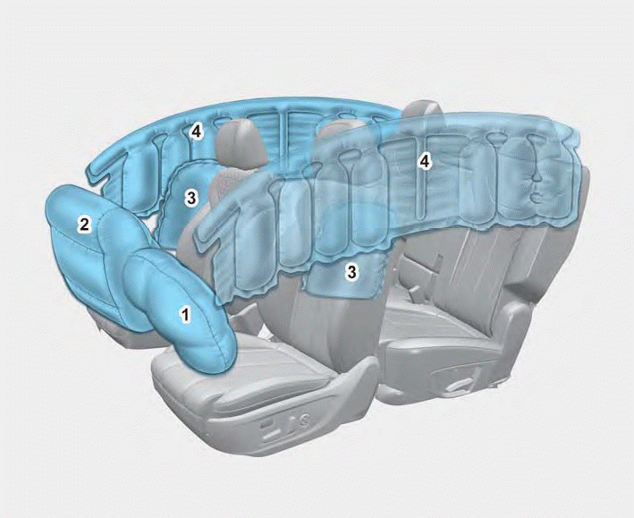
1. Driver’s front air bag
2. Passenger’s front air bag
3. Side air bag
4. Curtain air bag
The vehicles are equipped with a Supplemental Air Bag System for the driver’s
seat and front passenger’s seats.
The front air bags are designed to supplement the three-point seat belts. For
these air bags to provide protection, the seat belts must be worn at all times when
driving.
read more
 Specifications


