Hyundai Santa Fe (TM): Advanced Driver Assistance System (ADAS) / Parking Distance Warning (PDW)
Description and operation
| Description |
| • |
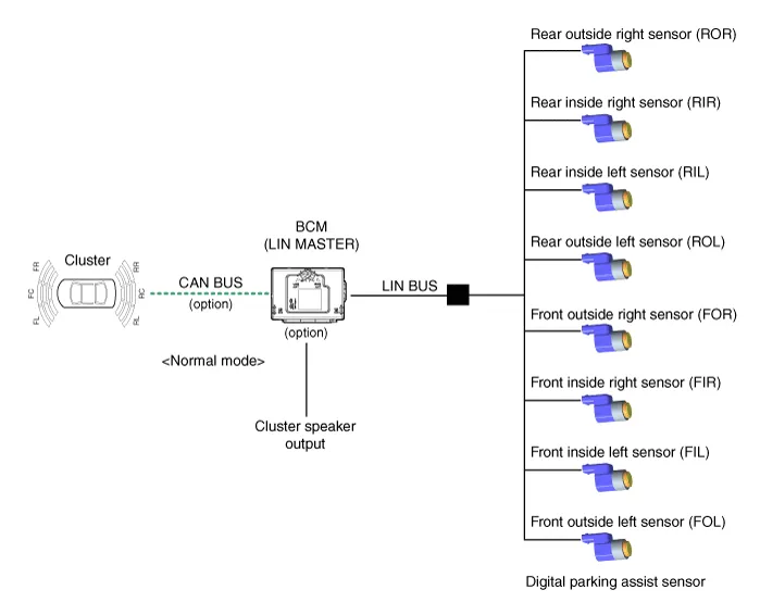
PDW consists of 8 sensors (front : 4 units, rear : 4 units) that are
used to detect obstacles and transmit the result in three separate warning
levels, the first, second and third to IBU via LIN communication.
|
| • |
IBU decides the alarm level by the transmitted communication message
from the slave sensors, then operates the buzzer or transmits the data
for display.
|
| Initial mode |
| 1. |
System initializing time
|
| 2. |
PDW recognizes LID and sets the sensor ID up during initialization.
|
| 3. |
PDW activates each sensor and then executes the diagnosis after finishing
initialization of IPM(IBU).
|
| 4. |
PDW starting buzzer is normally worked, when sensor does not send an
error message and after finishing error diagnosis.
|
| 5. |
If any failure is received from the any sensors, PDW starting buzzer
does not work but the failure alarm is operated for a moment.
If you have display option, warning sign is also shown on it.
|

| 6. |
IBU memorizes the completed initializing status of sensor.
|
| Normal mode |
| 1. |
PDW-F : Lin communication starts and keeps the routine after IGN1 ON+D
gear + below 10 km/h.
PDW-R : Lin communication starts and keeps the routine after IGN1 ON+R
gear
|
| 2. |
After initializing, the routine starts at once without PDW starting
warning sound.
|
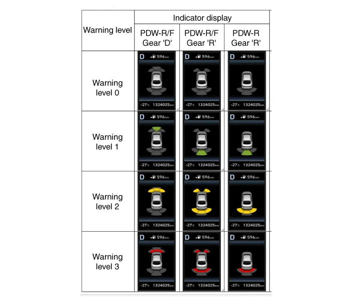
| 3. |
Alarms of obstacle consists of 3 level 1,2,3 step and 1,2 alarm sounds
intermittently and 3 alarm sounds continuously. 1 level alarm doesn't
exist in the front ultrasonic sensor.
|
| 4. |
In display, the data of each sensor is sent from IBU to display, for
example cluster. CAN communication is used for transmission and maximum
gateway time is 50ms.
|
| 5. |
The efficient vehicle speed of PDW operation is under 10Km/h.
|
| 6. |
Operation doesn't start or stops at gear N, P.
|
|
Level |
Distance range |
Allowed range |
|
1 |
Front : 61 - 100 cm (24.02 - 39.37 in.) / Rear : 61 - 120 cm (24.02 - 47.2
in.) |
± 15 cm (5.90 in.) |
|
2 |
31 - 60 cm (12.20 - 23.62 in.) |
± 15 cm (5.90 in.) |
|
3 |
0 - 30 cm (0 - 11.81 in) |
± 10 cm (3.94 in.) |
Components and components location
| Component Location |
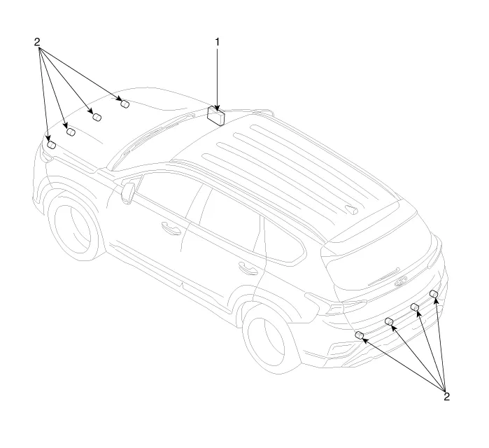
| 1. Integrated
Body Control Unit (IBU) |
2. Ultrasonic
Sensor |
Specifications
| Specifications |
|
Item |
Specification |
|
|
Ultrasonic sensor |
Voltage rating |
DC 12V |
|
Detecting range |
40cm ~ 120cm |
|
|
Operating voltage |
DC 9V ~ 16V |
|
|
Operation current |
MAX. 350mA |
|
|
Storage temperature |
-30°C ~ +80°C |
|
|
Operation temperature |
-40°C ~ +85°C |
|
|
Operation frequency |
48 ± 5 KHz |
|
|
Number of sensors |
12 units |
|
|
Item |
Specification |
|
|
Ultrasonic sensor |
Voltage rating |
DC 12V |
|
Detecting range |
40cm ~ 120cm |
|
|
Operating voltage |
DC 9V ~ 16V |
|
|
Operation current |
MAX. 40mA |
|
|
Storage temperature |
-30°C ~ +80°C |
|
|
Operation temperature |
-40°C ~ +85°C |
|
|
Operation frequency |
51.2 KHz |
|
|
Number of sensors |
4 or 8 Units |
|
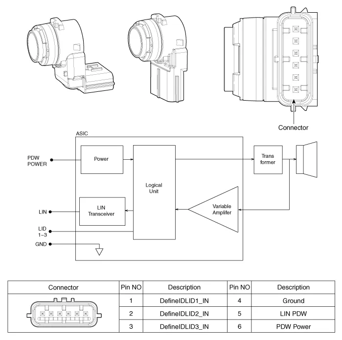
Ultrasonic Sensor. Schematic diagrams
| Schematic Diagrams |
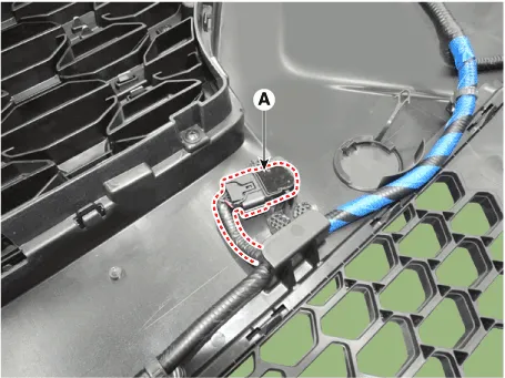
Ultrasonic Sensor. Repair procedures
| Removal |
| 1. |
Disconnect the negative (-) battery terminal.
|
| 2. |
Remove the front/rear bumper.
(Refer to Body - "Front Bumper Cover")
(Refer to Body - "Rear Bumper Cover")
|
| 3. |
Disconnect the connector from the parking distance warning sensor.
|
| 4. |
Pull out the sensor (A) by opening the sensor holder out.
|
| Installation |
| 1. |
Install the Parking distance warning sensor after connecting the connector.
|
| 2. |
Install the front/rear bumper cover.
|
| 3. |
Connect the negative (-) battery terminal.
|
Description and operation Description Rear Corner Radar is a system that measures the relative speed and distance from the following vehicles by using two electromagnetic wave radar sensors attached to the rear bumper, and detects any vehicle within the blind spot zone and gives off alarm.
Description and operation Description Surround View Monitor (SVM) is the system that allows video monitoring of 360 degrees around the vehicle.
Other information:
Hyundai Santa Fe (TM) 2019-2023 Service and Repair Manual: Power Windows
Description and operation Function Of Safety Power Window When driver door power window auto-up switch is operated, safety function is activated. 1. Safety function condition When detect the force of 100N (using the 10N/mm spring) during the window rising, window is reversed.
Hyundai Santa Fe (TM) 2019-2023 Service and Repair Manual: Button Engine Start System
Description and operation Description System Overview The System offers the following features: – Changing the state of engine ignition and power by using the start button. – Controlling external relays for ACC / IGN1 / IGN2 terminal switching and STARTER, without use
Categories
- Manuals Home
- Hyundai Santa Fe Owners Manual
- Hyundai Santa Fe Service Manual
- Auto Hold. Warning messages
- Emission Control System
- Automatic Transaxle Control System
- New on site
- Most important about car
