Hyundai Santa Fe (TM): Brake System / Master Cylinder. Components and components location
| Components |
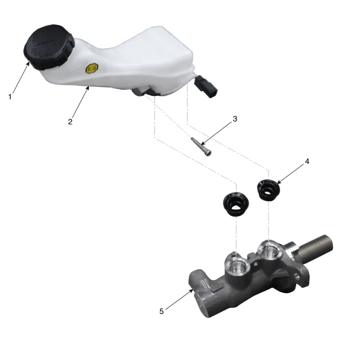
| 1. Reservoir
cap 2. Reservoir 3. Reservoir pin |
4. Grommet 5. Master cylinder |
Brake Booster Operating Test 1. Run the engine for one or two minutes, and then stop it. If the pedal depresses fully the first time but gradually becomes higher when depressed succeeding times, the booster is operating properly, if the pedal height remains unchanged, the booster is inoperative.
Removal 1. Turm ignition switch OFF and disconnect the negative (-) battery cable. 2. Remove the battery.
Other information:
Hyundai Santa Fe (TM) 2019-2023 Service and Repair Manual: Components and components location
Component Location (1) 1. Integrated Body Control Unit (IBU) 2. Buzzer 3. Door outside handle 4. Interior antenna 2 5. Door module antenna 6. Interior antenna 1 Component Location (2) 1.
Hyundai Santa Fe (TM) 2019-2023 Service and Repair Manual: Compressor. Components and components location
Components [Diesel 2.2 TCI-R] 1. Clutch Bolt 2. Disc & Hub Assembly 3. Clutch Spacer 4. Snap Ring 5. Pulley 6. Magnetic Coil Assembly 7. Compressor 8. Electric Control Valve (ECV) spacer 9.
Categories
- Manuals Home
- Hyundai Santa Fe Owners Manual
- Hyundai Santa Fe Service Manual
- Lane Following Assist (LFA)
- 4 Wheel Drive (4WD) System
- Auto Hold. Warning messages
- New on site
- Most important about car
