Hyundai Santa Fe: Emergency Call System / Emergency Call (eCall) Unit. Repair procedures
Hyundai Santa Fe (TM) 2019-2025 Service Manual / Body Electrical System / Emergency Call System / Emergency Call (eCall) Unit. Repair procedures
| Removal |
|
| 1. |
Disconnect the negative (-) battery terminal.
|
| 2. |
Remove the crash pad cnter panel.
(Refer to Body - "Crash Pad Center Panel")
|
| 3. |
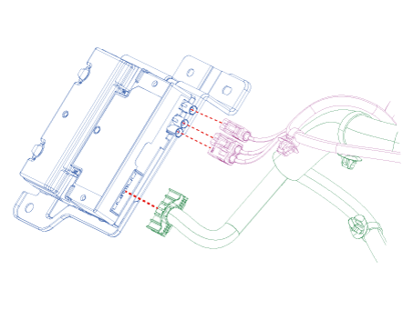
Disconnect ecall unit connectors.
|
| 4. |
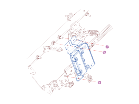
Remove the ecall unit after loosening mounting nuts.
|
| Replacement |
e-Call Unit Back Up Battery
| 1. |
Disconnect the negative (-) battery terminal.
|
| 2. |
Remove the eCall Unit.
|
| 3. |
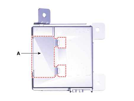
If it is necessary to replace the back-up battery, remove the back-up
battery cover (A).
|
| 4. |
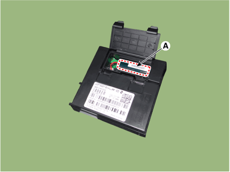
Replace the back-up battery (A).
|
| Installation |
If RED LED is on, check the eCall system with the diagnostic tools.
|
eCall Unit
| 1. |
Install the eCall unit.
|
| 2. |
Install the crash pad center panel.
|
| 3. |
Connect the negative (-) battery terminal.
|
| 4. |
Perform the "eCall Parameter Download"
(Refer to Inspection - " Inspection with Diagnostic Tools")
|
| Inspection |
Inspecting Back-Up Battery
Back-up battery (BUB) embedded in the eCall system has a finite lifespan and
using it for a long time may decrease its charging/discharging performance.
The back-up battery guarantees the operation of the eCall system when the vehicle
battery cannot be used due to an accident. Be sure to inspect the back-up battery
if the red LED turns on and replace it if necessary.
|
|
|
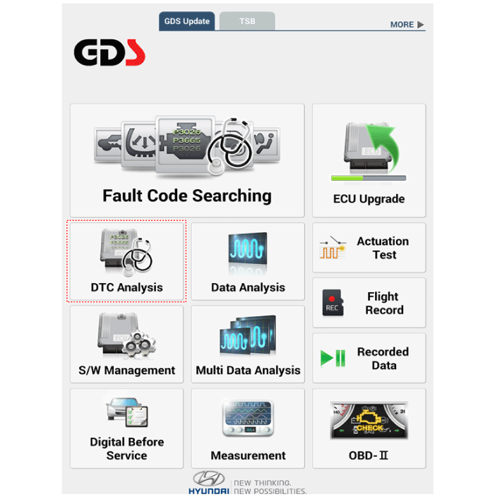
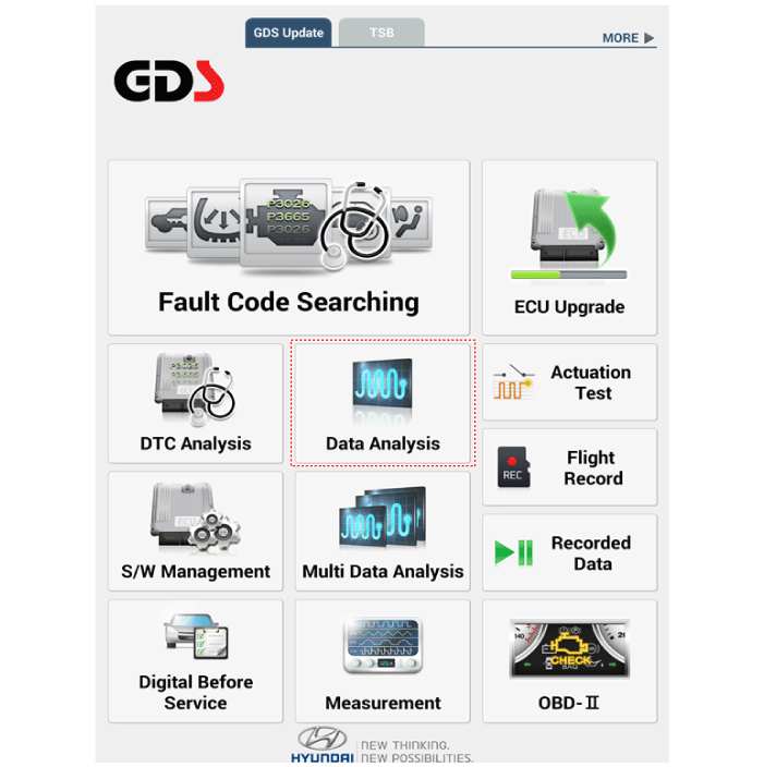
Inspection with Diagnostic Tools
In the eCall system, failure can be quickly diagnosed by using the vehicle diagnostic
system.
The diagnostic system provides the following information.
| 1) |
Self diagnosis : Checking failure and code number (DTC)
|
| 2) |
Current data : Checking the system input/output data state
|
| 1. |
Select the "Car Model" and the "eCall System" to be checked in order
to check the vehicle with the tester.
|
| 2. |
To inquire the cause of trouble for each module by self diagnosis, select
'Diagnostic Trouble Code'.
|
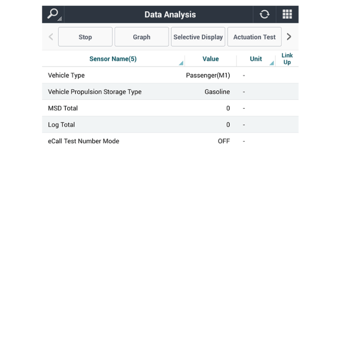
| 3. |
Select the 'Current Data' menu to check the current state of the input/output
data.
|
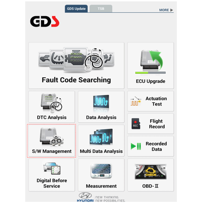
eCall System Reset
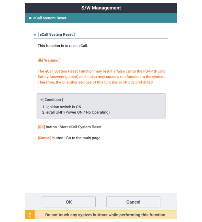
The eCall System Reset function is to reset when eCall is locked or stopped.
|
| 1. |
Turn the ignition switch OFF.
|
| 2. |
Connect the diagnostic tools.
|
| 3. |
Turn the ignition switch ON without the engine running.
|
| 4. |
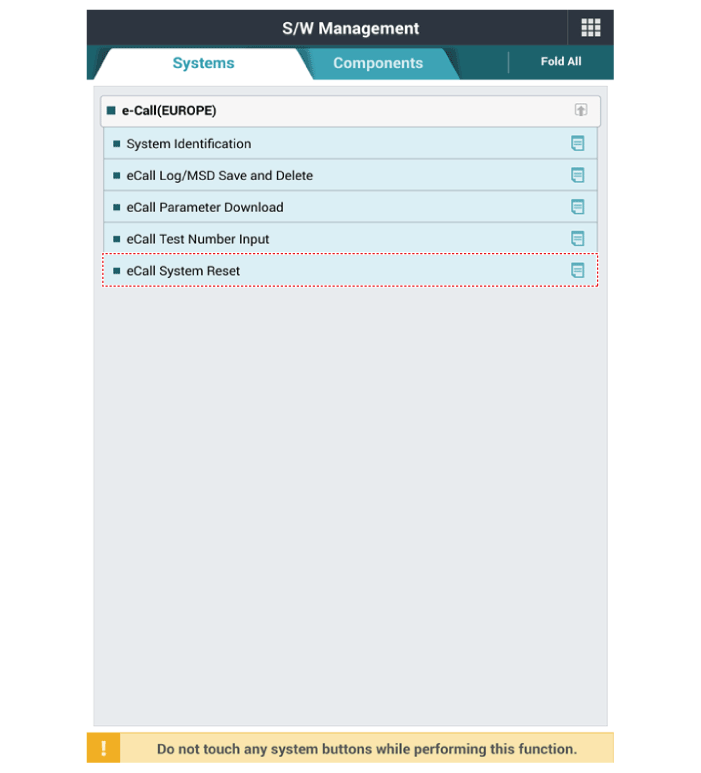
Select the "Car Model" and "S/W Management".
|
| 5. |
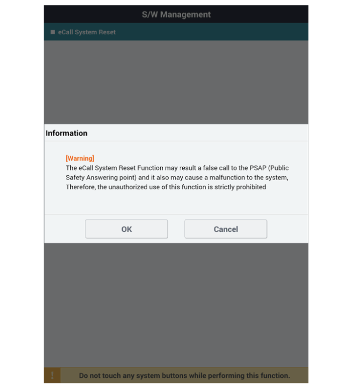
Select the "eCall System Reset"
|
| 6. |
Follow the screen instructions to perform the "eCall System Reset".
|
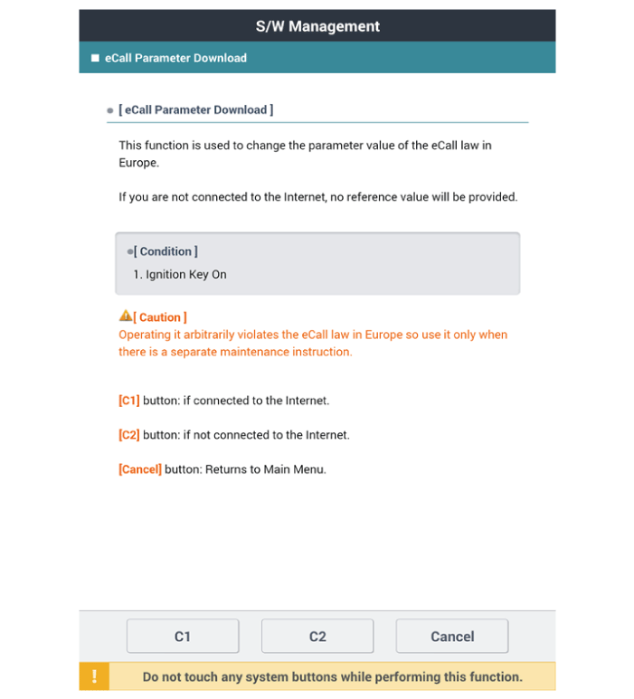
eCall Parameter Download
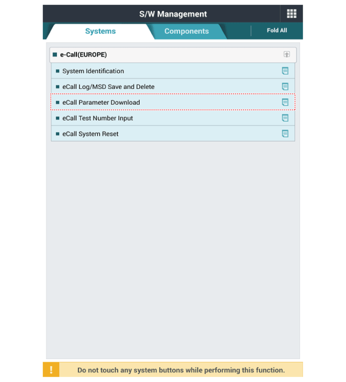
eCall Parameter Download is used to change the parameter value of the eCall
law in Europe.
| 1. |
Turn the ignition switch OFF.
|
| 2. |
Connect the diagnostic tools.
|
| 3. |
Turn the ignition switch ON without the engine running.
|
| 4. |
Select the "Car Model" and "S/W Management".
|
| 5. |
Select the "eCall Parameter Download"
|
| 6. |
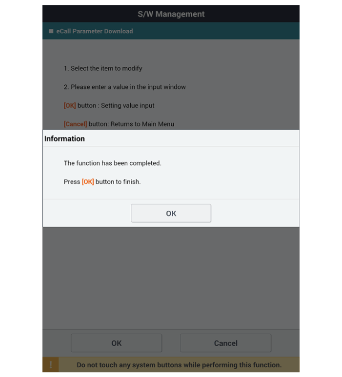
Follow the screen instructions to perform the "eCall Parameter Download".
|
Other information:
Hyundai Santa Fe (TM) 2019-2025 Service Manual: Specifications
Specification [Throttle Position Sensor (TPS)] Throttle Angle (°) Output Voltage (V) TPS1 TPS2 0 0.0 5.0 10 0...
Hyundai Santa Fe (TM) 2019-2025 Owner's Manual: Child-protector rear door locks
The child safety lock is provided to help prevent children seated in the rear from accidentally opening the rear doors. The rear door safety locks should be used whenever children are in the vehicle. The child safety lock is located on the edge of each rear door...
Categories
- Manuals Home
- 4th Generation Santa Fe Owners Manual
- 4th Generation Santa Fe Service Manual
- Head-up display settings
- Gauges and meters
- Side air bags
- New on site
- Most important about car
Instrument panel overview
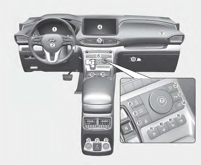
1. Instrument cluster
2. Driver’s front air bag
3. Engine Start/Stop button
4. Infotainment system
5. Hazard warning lamp switch
6. Climate control system
7. Shift button
8. ISG (Idle Stop and Go) button
9. Auto Hold button
10. Heated steering wheel button
11. Drive mode button
12. DBC (Downhill Brake Control) button
13. Parking Safety button
14. Parking/View button
15. Air ventilation seat button
16. Seat warmer
17. Passenger’s front air bag
18. Glove box
19. Wireless charging system pad
20. Cup holder
21. AC inverter
22. USB charger
Copyright © 2025 www.hsafe4.com


