Hyundai Santa Fe: Engine Control System / Accelerator Position Sensor (APS). Repair procedures
Hyundai Santa Fe (TM) 2019-2025 Service Manual / Engine Control/Fuel System / Engine Control System / Accelerator Position Sensor (APS). Repair procedures
| Inspection |
| 1. |
Connect the diagnostic tool on the Data Link Connector (DLC).
|
| 2. |
Turn the ignition switch ON.
|
| 3. |
Measure the output voltage of the APS 1 and 2 at C.T and W.O.T.
|
|||||||||||
| Removal |
| 1. |
Turn the ignition switch OFF and disconnect the battery (-) terminal.
|
| 2. |
Disconnect the accelerator position snesor connector (A).
|
| 3. |
Disconnect the mounting cap (A).
|
| 4. |
Remove the accelerator pedal module from the vehicle after loosening
the mounting bolt (A).
|
| Installation |
| 1. |
Install in the reverse order of removal.
|

 Injector. Description and operation
Description
Based on information from various sensors, the ECM can calculate the fuel amount
to be injected. The fuel injector is a solenoid-operated valve and the fuel
injection amount is controlled by length of injection time...
Other information:
Hyundai Santa Fe (TM) 2019-2025 Owner's Manual: Folding the side view mirror
Manual type To fold the side view mirror, grasp the housing of the mirror and then fold it toward the rear of the vehicle. Electric type The side view mirror can be folded or unfolded by pressing the switch. If 'Convenience -> Welcome mirror/light -> On door unlock' is selected in the User Settings mode on the LCD display, the outside mirror will fold or unfold automatically as follows: - The mirror will fold or unfold when the door is locked or unlocked by the smart key...
Hyundai Santa Fe (TM) 2019-2025 Owner's Manual: Rear window wiper and washer
The rear window wiper and washer switch is located at the end of the wiper and washer switch lever. Turn the switch to the desired position to operate the rear wiper and washer. HI – High wiper speed LO – Low wiper speed OFF – Off Push the lever away from you to spray rear washer fluid and to run the rear wipers 1~3 cycles...
Categories
- Manuals Home
- 4th Generation Santa Fe Owners Manual
- 4th Generation Santa Fe Service Manual
- Electronic child safety lock
- Warning and indicator lights
- Instrument cluster
- New on site
- Most important about car
Instrument panel overview
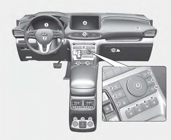
1. Instrument cluster
2. Driver’s front air bag
3. Engine Start/Stop button
4. Infotainment system
5. Hazard warning lamp switch
6. Climate control system
7. Shift button
8. ISG (Idle Stop and Go) button
9. Auto Hold button
10. Heated steering wheel button
11. Drive mode button
12. DBC (Downhill Brake Control) button
13. Parking Safety button
14. Parking/View button
15. Air ventilation seat button
16. Seat warmer
17. Passenger’s front air bag
18. Glove box
19. Wireless charging system pad
20. Cup holder
21. AC inverter
22. USB charger

Copyright © 2025 www.hsafe4.com