Hyundai Santa Fe (TM): Seat Electrical / Seat Heater Switch. Components and components location
| Components |
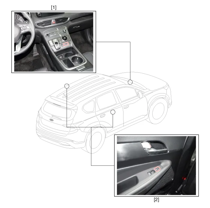
| 1. Front seat
heater switch |
2. Rear seat
heater switch |
Removal 1. Disconnect the negative (-) battery terminal. 2. Remove the front seat back cover.
Circuit Diagram Connector Pin Information Pin Description Pin Description 1 C-CAN (High) 21 ILL (+) 2 C-CAN (Low) 22 - 3 - 23 ILL (-) 4 - 24 Right seat heater signal 5 - 25 Right seat heater IND MIN 6 IGN 26 Right seat heater IND MID 7 - 27 Right seat heater IND MAX 8 Auto hold signal 28 Right ventilation seat signal 9 PDW signal 29 Right ventilation seat IND MIN 10 Steering wheel heater signal 30 Right ventilation seat IND MID 11 SVM signal 31 Right ventilation seat IND MAX 12 ISG signal 32 Left seat heater signal 13 DBC signal 33 Left seat heater IND MIN 14 - 34 Left seat heater IND MID 15 Steering wheel heater IND 35 Left seat heater IND MAX 16 ISG IND 36 Left ventilation seat signal 17 PDW IND 37 Left ventilation seat IND MIN 18 DETENT signal 38 Left ventilation seat IND MID 19 - 39 Left ventilation seat IND MAX 20 Ground 40 -
Other information:
Hyundai Santa Fe (TM) 2019-2023 Service and Repair Manual: Front View Camera Unit. Repair procedures
Removal 1. Disconnect the negative (-) battery terminal. 2. Remove the inside rear view mirror cover (A) and front view camera cover (B). 3.
Hyundai Santa Fe (TM) 2019-2023 Service and Repair Manual: Warning Indicator. Repair procedures
Inspection 1. Disconnect the negative (-) battery terminal. 2. Remove the front door trim. (Refer to Body - "Front door trim") 3. Disconnect the power door mirror connector from the harness BCW indicator
Categories
- Manuals Home
- Hyundai Santa Fe Owners Manual
- Hyundai Santa Fe Service Manual
- General Information
- Instrument cluster
- Maintenance
- New on site
- Most important about car