Hyundai Santa Fe (TM): Rear Driveshaft Assembly / Repair procedures
Hyundai Santa Fe (TM) 2019-2023 Service and Repair Manual / Driveshaft and axle / Rear Driveshaft Assembly / Repair procedures
| Removal |
|

| 1. |
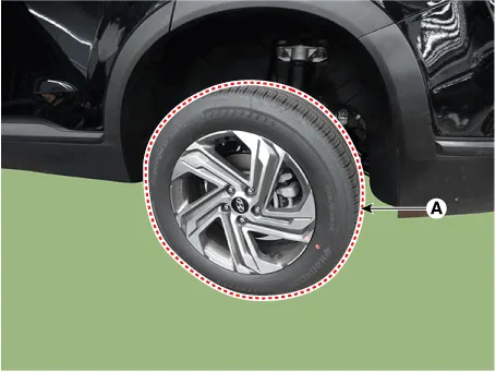
Loosen the wheel nuts slightly.
Raise the vehicle, and make sure it is securely supported.
|
| 2. |
Remove the rear wheel and tire (A) from rear hub.
|

| 3. |
Remove the rear brake caliper.
(Refer to Brake System - "Rear Disc Brake")
|
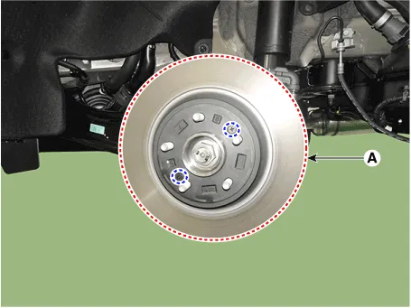
| 4. |
Loosen the screw and then removing the rear brake disc (A).
|
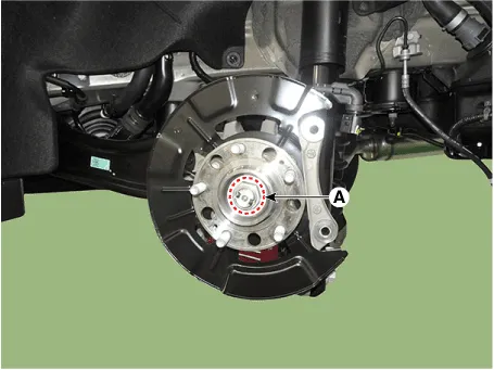
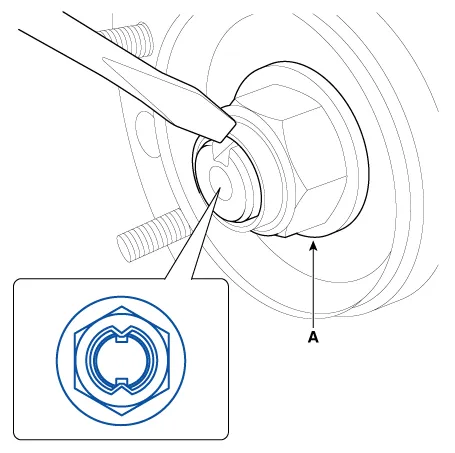
| 5. |
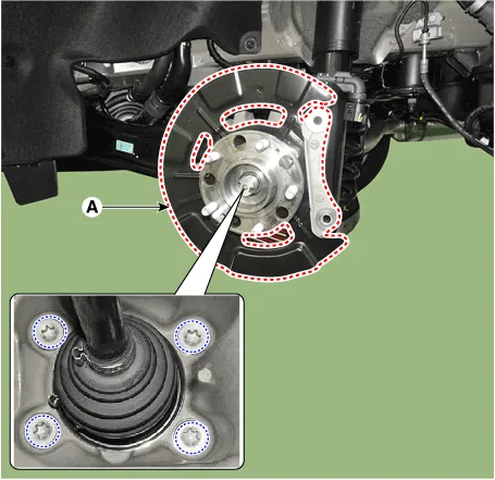
Loosen the driveshaft caulking nut (A) from the rear hub.
|
| 6. |
Remove the rear hub assembly and dust cover (A) after loosening the
mounting bolts.
|
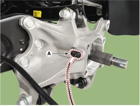
| 7. |
Remove the rear wheel speed sensor (A) after loosening the mounting
bolt.
|
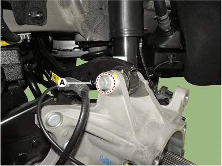
| 8. |
Remove the rear upper arm from the rear carrier after loosening the
bolt and nut (A).
|
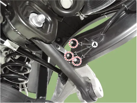
| 9. |
Remove the trailing arm from the rear carrier after loosening the mounting
nuts (A).
|
| 10. |
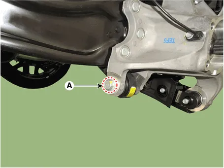
Remove the rear assist arm from the rear carrier after loosening the
bolt and nut (A).
|
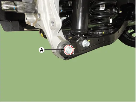
| 11. |
Remove the rear lower arm from the rear carrier after loosening the
bolt and nut (A).
|
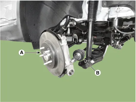
| 12. |
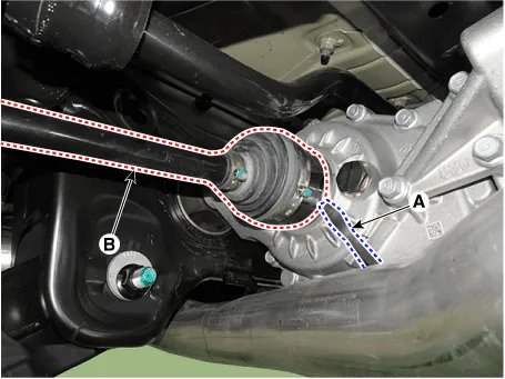
Remove the rear drive shaft (B) from the rear axle assembly (A).
|
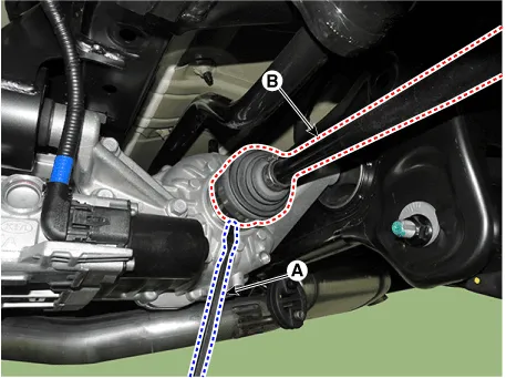
| 13. |
Remove the rear drive shaft (B) from the differential by using the pry
bar (A).
[LH]
[RH]
|
| Inspection |
| 1. |
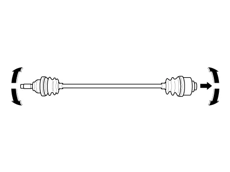
Check the driveshaft boots for damage and deterioration.
|
| 2. |
Check the ball joint for wear and damage.
|
| 3. |
Check the splines for wear and damage.
|
| 4. |
Check the driveshaft for cracks and wears.
|
| 5. |
Check the TJ outer race, inner race, cage and balls for rust or damage.
|
| 6. |
Check for water, foreign matter, or rust in the BJ boot.
|
| Disassembly |
|
| 1. |
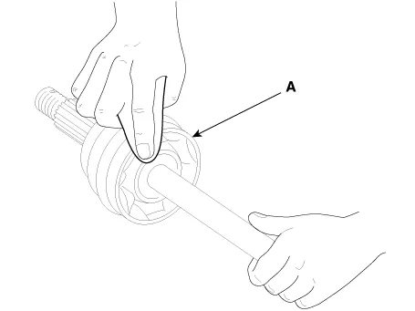
Remove the TJ boot bands and pull the TJ boot from the TJ outer race.
|
| 2. |
Pull out the driveshaft from the TJ outer race.
|
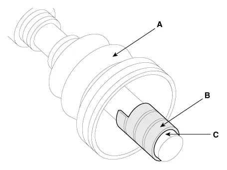
| 3. |
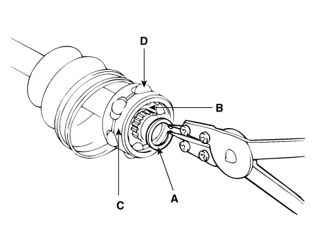
Remove the snap ring (A) and take out the inner race(B), cage(C) and
balls(D) as an assembly.
|
| 4. |
Clean the inner race, cage and balls without disassembling.
|
| 5. |
Remove the BJ boot bands and pull out the TJ boot and BJ boot.
|
| Reassembly |
| 1. |
Wrap tape around the driveshaft splines (TJ side ) to prevent damage
to the boots.
|
| 2. |
Apply grease to the driveshaft and install the boots.
|
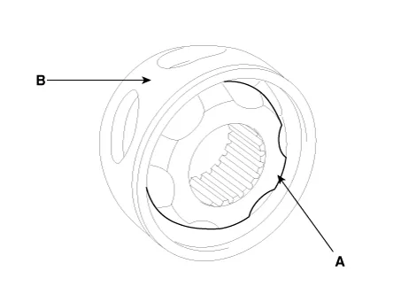
| 3. |
Apply the specified grease to the inner race (A) and cage (B). Install
the cage (B) so that it is offset on the race as shown.
|
| 4. |
Apply the specified grease to the cage and fit the balls into the cage.
|
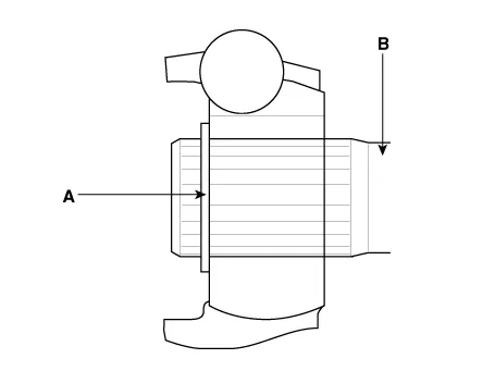
| 5. |
Position the chamfered side (A) as shown in the illustration. Install
the inner race on the driveshaft(B), and then the snap ring.
|
| 6. |
Apply the specified grease to the outer race and install the BJ outer
race onto the driveshaft.
|
| 7. |
Apply the specified grease into the TJ boot and install the boot with
a clip.
|
| 8. |
Tighten the TJ boot bands.
|
| 9. |
Add the specified grease to the BJ as much as wiped away at inspection.
|
| 10. |
Install the boots.
|
| 11. |
Tighten the BJ boot bands.
|
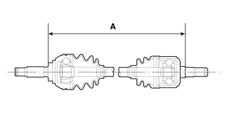
| 12. |
To control the air in the TJ boot, keep the specified distance between
the boot bands when they are tightened.
|
| Installation |
| 1. |
To install, reverse the removal procedures.
|
| 2. |
Check the alignment.
(Refer to Suspension System - "Alingment")
|
Components 1. Rear drive shaft (left) 2. Rear drive shaft (right)
Other information:
Hyundai Santa Fe (TM) 2019-2023 Service and Repair Manual: Special service tools
Special Service Tools Tool Name / Number Illustration Description LKA Compensator (09890-3V100) Used for compensating front view camera unit Vertical measuring instrument (09964-C1200) Used to measure l
Hyundai Santa Fe (TM) 2019-2023 Service and Repair Manual: Description and operation
Description and operation The System may be limited when • The radar sensor or camera is blocked with a foreign object or debris.
Categories
- Manuals Home
- Hyundai Santa Fe Owners Manual
- Hyundai Santa Fe Service Manual
- Forward Collision-Avoidance Assist Settings
- Fender Garnish. Repair procedures
- Heating,Ventilation And Air Conditioning
- New on site
- Most important about car

Copyright © 2025 www.hsafe4.com - 0.0185