Hyundai Santa Fe (TM): IMS (Integrated Memory) / IMS (Integrated Memory System) module. Repair procedures
| Removal |
| 1. |
Remove the negative (-) battery terminal.
|
| 2. |
Remove the front seat assembly.
(Refer to Body - "Front Seat Assembly")
|
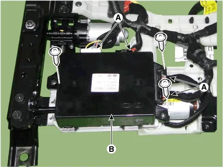
| 3. |
Remove the IMS module (B) after disconnecting the connector (A) and
loosening the screws (3EA).
|
| Installation |
| 1. |
Install the IMS module after reconnecting the connector.
|
| 2. |
Install the driver seat.
|

Components IMS input/output pin information No Connector A Connector B Connector C 1 Cushion extension moter (Forward) B+ (Power) Seat slide motor switch (Forward) 2 Seat recline motor (Forward) Ground (Power) Seat recline switch (Forward) 3 Seat height motor (Up) B+ (Power) Seat tilt switch (Up) 4 Seat slide motor(Forward) - Seat height switch (Up) 5 Seat Cushion extension moter (Backward) Ground Seat cushion extension switch (Forward) 6 Seat recline motor (Backward) B_CAN (High) 7 Seat tilt motor (Up) B_CAN (Low) 8 Seat tilt motor (Down) Driver lumber support motor (Up) 9 Seat height motor (Down) Driver lumber support motor (Mid) 10 Seat slide motor (Backward) Seat slide sensor 11 Seat tilt sensor 12 Seat recline limit switch (Forward) 13 Seat position sensor power 14 IGN 1 15 Seat slide switch (Backward) 16 Seat recline switch (Backward) 17 Seat tilt switch (Down) 18 Seat height switch (Down) 19 Seat cushion extension switch (Backward) 20 Ground 21 Driver lumber support motor (Low) 22 - 23 Driver lumber support motor (Def) 24 Seat recline sensor 25 Seat height sensor 26 Seat cushion extension limit sensor 27 Seat recline limit switch (Backward) 28 Battery (+) Circuit Diagram
Other information:
Hyundai Santa Fe (TM) 2019-2023 Service and Repair Manual: Rear Heater Unit. Components and components location
Component Location 1. Rear Heater & A/C Unit Components 1. Rear heater & blower unit assembly 2. Blower motor assembly 3. Rear power mosfet 4. Duct seal guide 5.
Hyundai Santa Fe (TM) 2019-2023 Service and Repair Manual: Description and operation
Description Back view camera will activate when the backup light is ON with the ignition switch ON and the shift lever in the R position. This system is a supplemental system that shows behind the vehicle through the H/UNIT or the ECM (Reverse Display Room Mirror) mirror while backing-up.