
Hyundai Santa Fe (TM): Engine Control System / Knock Sensor (KS). Repair procedures
Hyundai Santa Fe (TM) 2019-2023 Service and Repair Manual / Engine Control/Fuel System / Engine Control System / Knock Sensor (KS). Repair procedures
| Removal |
| 1. |
Turn the ignition switch OFF and disconnect the battery negative (-)
cable.
|
| 2. |
Remove the intake manifold.
(Refer to Engine Mechanical System - "Intake Manifold")
|
| 3. |
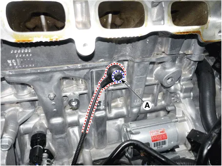
Remove the installation bolt (A), and then remove the sensor from the
cylinder block.
|
| Installation |
|

| 1. |
Installation is reverse of removal.
|
Circuit Diagram Harness Connector
Description Heated Oxygen Sensor (HO2S) consists of zirconium and alumina and is installed both upstream and downstream of the Manifold Catalytic Converter.
Other information:
Hyundai Santa Fe (TM) 2019-2023 Service and Repair Manual: Refrigerant Line. Repair procedures
Replacement [Front suction & Liquid pipe assembly] 1. If a compressor is available, the air conditioner is operated for a few minutes in the engine idle state and then the engine is stopped. 2.
Hyundai Santa Fe (TM) 2019-2023 Service and Repair Manual: Condenser. Repair procedures
Inspection 1. Check the condenser fins for clogging and damage. If clogged, clean them with water, and blow them with compressed air. If bent, gently bend them using a screwdriver or pliers. 2.
Categories
- Manuals Home
- Hyundai Santa Fe Owners Manual
- Hyundai Santa Fe Service Manual
- Engine Control/Fuel System
- Identification Numbers
- Troubleshooting
- New on site
- Most important about car

Copyright © 2026 www.hsafe4.com - 0.0232